2025年8月,上海交通大学机械与动力工程学院张文明教授团队以「Piezoelectric active air-cooling devices」为题在Chip上发表长篇综述论文,系统阐述了压电主动风冷散热技术的工作原理、结构设计与性能优化策略。第一作者为硕士生彭泊洋,通讯作者为易志然助理研究员和张文明教授。
随着电子器件功耗密度急剧攀升与微型化趋势的加速,传统散热方式(如被动散热、旋转风扇)在空间受限的高性能芯片、射频模块及AI芯片中已难以满足高热流密度的散热需求。压电主动风冷技术因具备低功耗、高响应速度、无电磁干扰及结构紧凑等优势,正成为下一代微系统热管理的变革性解决方案。
技术原理与典型结构
压电冷却技术的物理核心是逆压电效应。当在压电陶瓷(如锆钛酸铅PZT)等材料上施加交变电场时,其晶格结构会发生周期性变形,产生微米级的位移或弯曲。这种将电能直接转换为机械能的特性,使得压电致动器具有响应速度快(毫秒级)、能量密度高、位移分辨率极高且不产生电磁干扰的先天优势。压电冷却器件通过精妙的机械结构设计,将这种微幅高频振动转化为有效的空气流动,其主要技术路径可分为三类:压电风扇、零净质量射流型冷却器和非零净质量射流型冷却器。
压电风扇(Piezoelectric Fan)是最早被研究的类型,如图1a所示,其结构相对简单,通常由一个粘贴有压电陶瓷片的悬臂梁构成。在交流电压驱动下,压电片的周期性形变带动悬臂梁以其共振频率进行大振幅的往复摆动,如同一个微型的“扇子”,直接搅动周围空气,产生定向气流。其最大优势在于结构开放,无需密闭腔体,即可产生单向气流。
零净质量射流(Zero-Net-Mass Jet),如图1b所示它由一个密闭腔体、一个振动膜(压电驱动)和一个或多个微孔组成。振动膜周期性地振动,交替地压缩和膨胀腔体容积:在排气冲程,腔内空气被高速挤压出微孔;在吸气冲程,腔内外压差使周围空气被吸入腔体。关键在于,在一个完整的振动周期内,射出的流体质量与吸入的流体质量相等,净质量为零,但其动量不为零。射出的涡环在自诱导作用下向下游移动,从而持续不断地卷吸周围流体,形成一股持续的射流。这种无需外部气源、仅从周围环境中“汲取”气体形成射流的特性,使其适合集成应用。
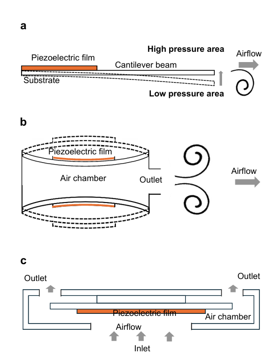
图1 三种不同类型的压电冷却装置的工作原理。
非零净质量射流(Non-Zero-Net-Mass Jet) 则旨在产生连续的、具有净质量流出的气流。如图1c所示,其核心特征在于具有独立的进、出口。通过腔体结构的不对称设计(如“虚拟阀”或“物理阀”),或多个腔体的协同工作,使得在一个周期内,从出口排出的空气量大于从出口吸入的空气量,从而产生净流出气流。这种设计能提供更高的流量和压力,尤其适用于需要克服较大流阻的散热场景。
图2 清晰地展示了商业压电散热装置的技术路线。左一对应了最经典的零净质量射流器件,亦可称为合成射流原理压电射流器。左二的“微鼓风机(Microblower)” 是改进型合成射流的典范,其将压电振膜与精密腔体集成于微型封装内,通过高频振动产生脉冲气流。 右二则是一种增强型非零净质量射流设计,它采用了多层腔体结构和独特的虚拟阀技术,能在小厚度下提供较高背压和流量。而右一代表了MEMS压电散热器件,其尺寸仅为9.26×7.6×1.08 mm³,采用半导体标准的薄膜压电技术和硅微加工工艺制造,实现了前所未有的小型化、集成化和一致性,为在空间和功耗都极度敏感的移动设备中实现主动散热提供了可能。
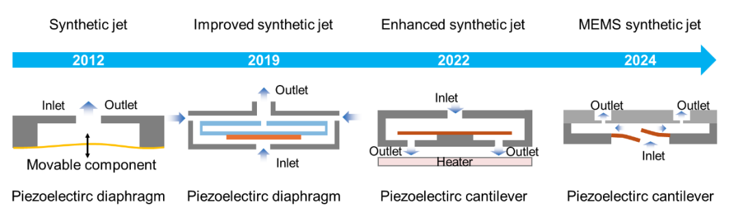
图2 压电主动冷却风扇的发展里程碑2-5。
系统集成与布局策略
将高性能的微型冷却器件有效地集成到电子系统中,是发挥其效能的关键一步。优化布局策略可以实现系统级的散热性能提升。
多器件协同工作是提升散热能力的有效途径。图3(a) 展示了串联式合成射流的设计,其核心在于对多个作动腔室的驱动信号进行相位控制。当两个腔室的驱动信号相位差为180°时,一个腔室处于吸气阶段,另一个则处于排气阶段,二者协同工作,如同一个“推挽”系统,能显著增强整体的净流量输出,实现1+1>2的效果。图3(b)则展示了并联式合成射流的设计,这种设计旨在减少射流器之间的串扰使得其流场调控效果便于叠加。
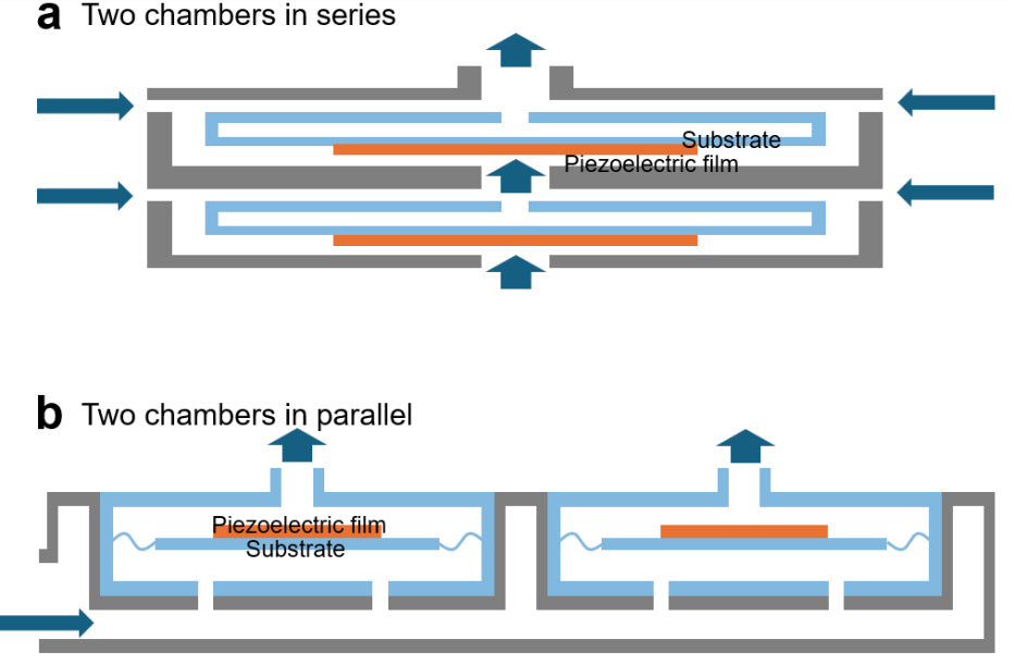
图3 多压电射流设计。a. 串联合成型非零净质量射流的示意图6。b. 并联射流设计的示意图7。
图4 则体现了另一项专利设计,展示了如何在系统层面优化气流组织。该设计将多个冷却模块并联,共享一个公共的外部进气通道。其精妙之处在于,冷却流体在流经整个模块时,会顺序接触各个冷却器件的外表面。这种布局不仅实现了均匀的热分散,将热量从多个点导出,还巧妙地利用器件外壳本身作为附加的散热面,极大地增强了系统的总体热耗散能力,实现了高效的空间利用和热管理效能的最大化。
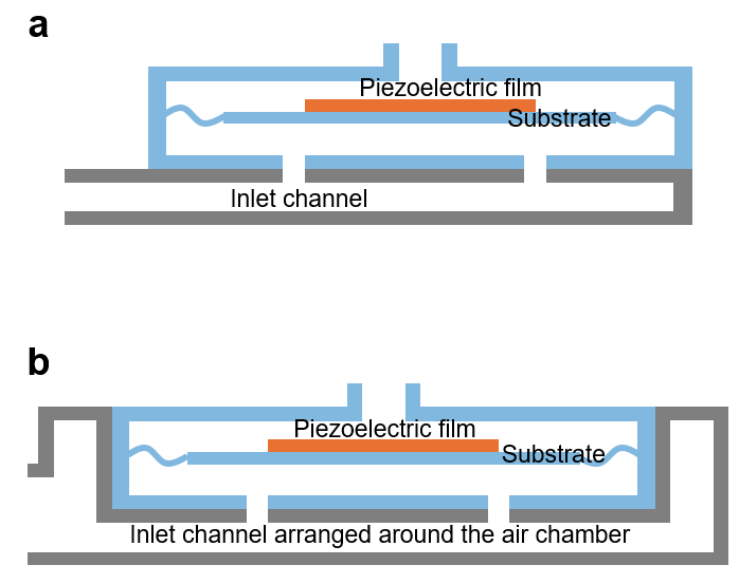
图4 流道优化专利设计示意图7。a. 将入口通道与外壳主外表面平行布置,以增强流体与外壳表面的接触,实现高效散热。b. 增加外部入口的高度以避免流动受限,并将流道布置在空气腔周围以增强散热效果。
前沿与展望:MEMS技术赋能微型化
压电冷却技术的终极发展目标是实现与芯片级的集成,为片上系统(SoC)提供原位散热。微机电系统(MEMS)制造技术正使这一愿景成为现实。
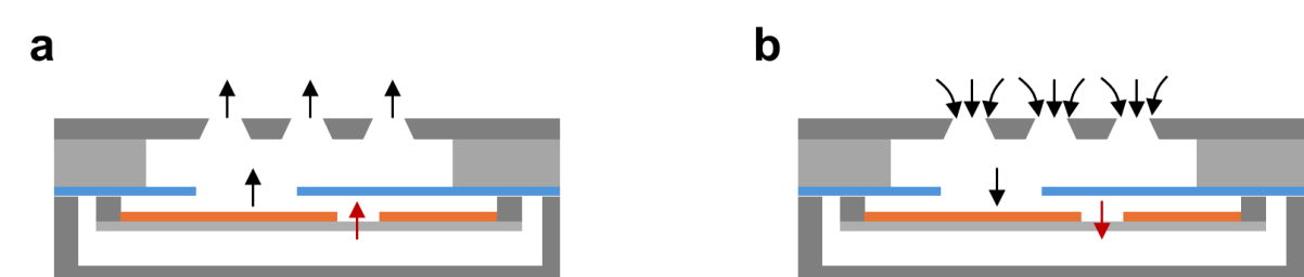
图5 展示了一款基于硅基压电MEMS执行器的合成射流冷却装置,是该领域前沿研究的典范。该器件利用半导体工艺,在硅晶圆上集成制造了压电(采用环保的氮化铝AIN薄膜替代传统的PZT)振膜和微米级气室结构。尽管其尺寸极小,但在仅5V的超低驱动电压下,功耗低于280mW,就能在1分钟内将一个85°C的热源温度降低20°C,同时产生2.7 m/s的气流速度。这种器件展现了无与伦比的功率密度和集成潜力,其制造工艺与IC芯片兼容,为未来将其直接封装在芯片上方或内部,实现对局部“热点”(Hot Spot)的精准扑灭提供了可行的技术路径,有望解决高性能处理器、射频模块等微型高功率元件的过热问题。
Piezoelectric active air-cooling devices¹
As the power density of electronic devices sharply increases and the trend toward miniaturization accelerates, traditional cooling methods (such as passive cooling and rotary fans) are struggling to meet the high heat flux dissipation requirements of space-constrained high-performance chips, RF modules, and AI chips. Piezoelectric active cooling technology, offering advantages such as low power consumption, high response speed, no electromagnetic interference, and compact structure, is emerging as a transformative solution for the thermal management of next-generation microsystems.
I. Operating Principles and Typical Structures
The physical core of piezoelectric cooling technology is the inverse piezoelectric effect. When an alternating electric field is applied to a material such as piezoelectric ceramics (e.g., Lead Zirconate Titanate, PZT), its lattice structure undergoes periodic deformation, generating micron-scale displacement or bending. This characteristic of directly converting electrical energy into mechanical energy endows piezoelectric actuators with inherent advantages, including fast response times (millisecond scale), high energy density, extremely high displacement resolution, and no electromagnetic interference. Piezoelectric cooling devices convert this small-amplitude, high-frequency vibration into effective air movement through sophisticated mechanical structure designs. The main technological approaches can be categorized into three types: piezoelectric fans, zero-net-mass jet coolers, and non-zero-net-mass jet coolers.
Piezoelectric Fans, the earliest type to be studied (as shown in Figure 1a), have a relatively simple structure, typically consisting of a cantilever beam with a piezoelectric ceramic patch bonded to it. Driven by an AC voltage, the periodic deformation of the piezoelectric patch causes the cantilever beam to oscillate with a large amplitude at its resonant frequency, acting like a miniature "fan" that directly agitates the surrounding air and generates directional airflow. Its greatest advantage lies in its open structure, which allows it to produce unidirectional airflow without the need for a sealed chamber.
Zero-Net-Mass Jets (as shown in Figure 1b) comprise a sealed cavity, a vibrating diaphragm (piezoelectrically actuated), and one or more small orifices. The diaphragm vibrates periodically, alternately compressing and expanding the cavity volume: during the expulsion stroke, air inside the cavity is forced out through the orifice at high speed; during the suction stroke, the pressure differential draws surrounding air into the cavity. Crucially, over a complete vibration cycle, the mass of fluid ejected equals the mass of fluid ingested—hence zero net mass—but the momentum is non-zero. The ejected vortex rings propagate downstream due to self-induced motion, continuously entraining surrounding fluid and forming a sustained jet. This characteristic of generating a jet without an external air source, by "ingesting" gas solely from the surrounding environment, makes it suitable for integrated applications.
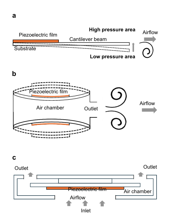
Fig. 1 | Principle of three different types of piezoelectric cooling device.
Non-Zero-Net-Mass Jets are designed to produce a continuous airflow with a net mass outflow. As shown in Figure 1c, their core feature is the presence of separate inlet and outlet ports. Through the asymmetrical design of the cavity structure (e.g., employing "virtual valves" or "physical valves"), or the coordinated operation of multiple cavities, the volume of air expelled from the outlet during a cycle exceeds the volume drawn in from the outlet, resulting in a net outflow. This design can deliver higher flow rates and pressures, making it particularly suitable for cooling scenarios that require overcoming significant flow resistance.
Figure 2 clearly illustrates the technological roadmap for commercial piezoelectric cooling devices. The leftmost image corresponds to the most classic zero-net-mass jet device, also known as a synthetic jet piezoelectric cooler. The second image from the left, the "Microblower," represents a refined synthetic jet design that integrates a piezoelectric diaphragm and a precision cavity into a miniature package, generating pulsed airflow through high-frequency vibration. The second image from the right showcases an enhanced non-zero-net-mass jet design, employing a multi-layer cavity structure and a unique virtual valve technology to provide relatively high back pressure and flow rate within a small thickness. The rightmost image represents MEMS piezoelectric cooling devices, exemplified by dimensions as small as 9.26 × 7.6 × 1.08 mm³. These are manufactured using standard semiconductor thin-film piezoelectric technology and silicon micromachining, achieving unprecedented miniaturization, integration, and consistency. This technology makes active cooling feasible for mobile devices where space and power consumption are extremely critical.
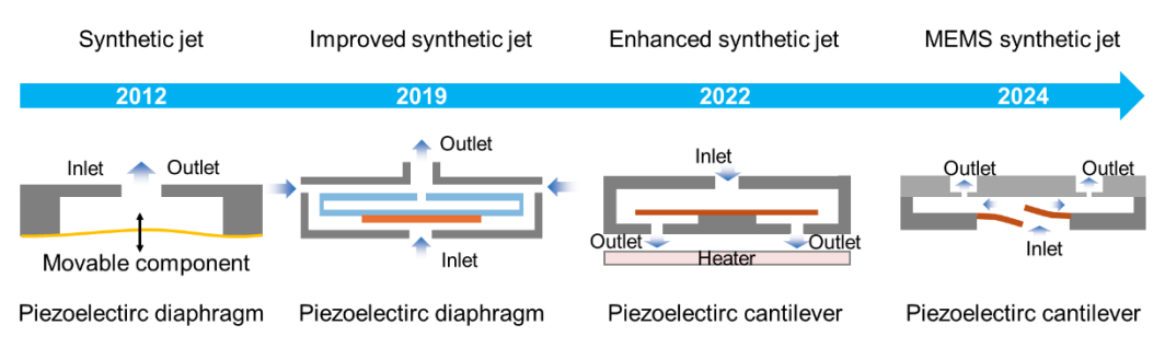
Figure 2 A milestone of piezoelectric active cooling fan2-5
II. System Integration and Arrangement Strategies
Effectively integrating high-performance miniature cooling devices into electronic systems is a critical step in realizing their potential. Optimized arrangement strategies can yield significant improvements in system-level thermal management performance.
Multi-Device Coordination is an effective way to enhance cooling capacity. Figure 3a illustrates a series-connected synthetic jet design, where the key is controlling the phase of the driving signals for multiple actuation chambers. When the driving signals for two chambers have a phase difference of 180°, one chamber is in the intake phase while the other is in the exhaust phase. They work together like a "push-pull" system, significantly enhancing the overall net flow output, achieving a 1+1>2 effect. Figure 3b shows a parallel synthetic jet design. This configuration aims to reduce crosstalk between individual jet actuators, making their flow field effects easier to superimpose.
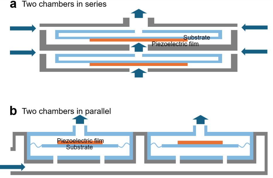
Figure 3 Multi-Piezojets designs. a. Schematic diagram of synthetic type non-zero-net-mass jet in series6. b. Schematic diagram of Murata's jets-in-parallel design7.
Figure 4 embodies another patented design, demonstrating how to optimize airflow organization at the system level. This design connects multiple cooling modules in parallel, sharing a common external inlet channel. The ingenuity lies in the fact that the cooling fluid, while flowing through the entire assembly, sequentially contacts the outer surfaces of the individual cooling device components. This arrangement not only achieves uniform heat spreading, drawing heat away from multiple points, but also cleverly utilizes the device housings themselves as additional heat dissipation surfaces. This greatly enhances the system's overall heat dissipation capacity, achieving efficient space utilization and maximizing thermal management effectiveness.
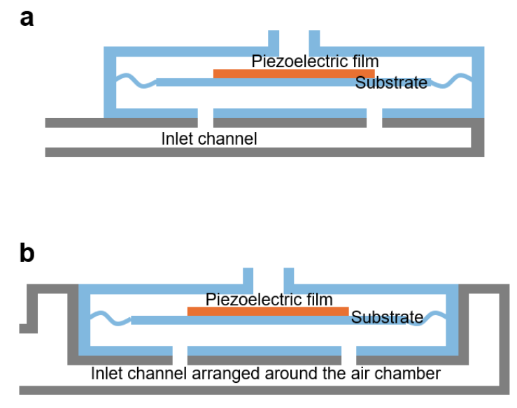
Figure 4 Schematic diagram of Murata's patent design7. a. Making the inlet channel parallel to the main outer surface of the housing enhances fluid contact with the surface of the housing for effective heat dissipation. b. The height of the external inlet is increased to avoid flow restriction, and the flow paths are arranged around the air chamber for more heat dissipation.
III. Frontiers and Outlook: MEMS Technology Enabling Miniaturization
The ultimate goal of piezoelectric cooling technology is to achieve on-chip integration, providing in-situ cooling for systems-on-chip (SoCs). micro-electro-mechanical system (MEMS) fabrication technology is turning this vision into reality.
Figure 5 showcases a synthetic jet cooling device based on a silicon-based piezoelectric MEMS actuator, representing a state-of-the-art research paradigm in this field. This device utilizes semiconductor processes to integrally fabricate the piezoelectric diaphragm (employing environmentally friendly aluminum nitride (AlN) thin film instead of traditional PZT) and a micron-scale cavity on a silicon wafer. Despite its extremely small size, driven by an ultra-low voltage of only 5 V and consuming less than 280 mW, it can reduce the temperature of an 85°C heat source by 20°C within one minute while generating an air velocity of 2.7 m/s. Such devices demonstrate unparalleled power density and integration potential. Their fabrication process is compatible with IC chip manufacturing, offering a feasible technological pathway for future direct packaging above or even within chips to precisely extinguish local "hot spots". This holds promise for solving the overheating problems in miniature, high-power components like high-performance processors and RF modules.
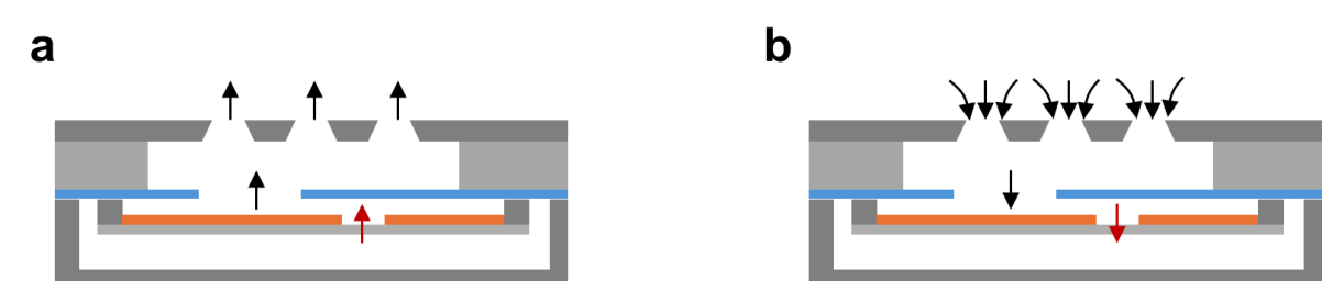
Figure 5 Synthetic jet working principle8. a. outlet process. b. inlet process.
参考文献
1. Peng, B. et al. Piezoelectric active cooling technology for high heat flux microsystems. Chip 5, 100163 (2026).
2. Wang, R.-T. et al. Design and testing of a bearing less piezo jet micro heat sink. J. Mar. Sci. Technol. 30, 180–191 (2022).
3. Wang, C.-P. Thermal management for portable electronics using a piezoelectric micro-blower. IEEE Trans. Device Mater. Reliab. 19, 563–567 (2019).
4. Ganti, S. et al. MEMS-based cooling systems for closed and open devices. CN patent CN113661568A (2020).
5. Nov. 2023. Liang, Z & Ren, J. Gas pulse generating device. CN patent CN117135543A (2023).
6. Liu, C. et al. Simulation and experimental study of direct spray type piezoelectric air pumps based on synthetic jet. Microsyst. Technol. 25, 4445–4454 (2019).
7. Okaguchi, K. Pump device. US patent US20220056900 A1 (2022).
8. Zhang, B. et al. A synthetic jets cooling device based on piezoelectric ALN Mems actuators. In 2024 IEEE 37th International Conference on Micro Electro Mechanical Systems (MEMS), 259–262 (IEEE, 2024).
论文链接:
https://doi.org/10.1016/j.chip.2025.100163


微信扫描下方的二维码阅读本文
- 热交换核心 :冷板(CPU/GPU专用)、CDU(冷量分配单元);
- 循环网络 :Manifold分液器、EPDM/PTFE管路、快接头;
- 动力与控制 :变频循环泵(如飞龙股份电子泵)、智能温控系统。